
Vacuum-tube-based image intensifier
Photek image intensifiers are vacuum tubes protected by an input window through which photons can enter and strike a photocathode inside. There, the photons are converted into electrons (photoelectrons, pe). In the Multi-Channel Plate (MCP), the photoelectrons are accelerated by a high voltage and, upon colliding with the walls of the MCP’s millions of channels, knock out additional electrons, thereby achieving the amplification effect. All electrons then strike a phosphor layer, where they are converted back into photons. Using various optical components, the outgoing signal can then be focused onto a detector or a high-speed camera to digitize the resulting image.
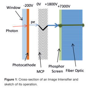


All of the components mentioned play an important role and can – or must—be adapted to the specific application. These details are outlined below, but we would be happy to discuss your application with you and work with you to select the best configuration.
Input window: Since most phosphors deposited on the surface of photocathodes are sensitive to our normal atmosphere, all image intensifiers are vacuum tubes, and light enters through a window. Quartz glass is used as the standard material; magnesium fluoride can also be used to operate in the shorter-wavelength UV range. Other options include various types of glass, such as sapphire, or fiber-optic couplings.
Photocathodes: A photocathode consists of a thin semiconductor layer in which photoelectrons are generated and accelerated. The spectral response determines the choice of semiconductor, since the generation of photoelectrons depends on the material and wavelength.
The figure shows the sensitivity curves of the possible photocathodes: 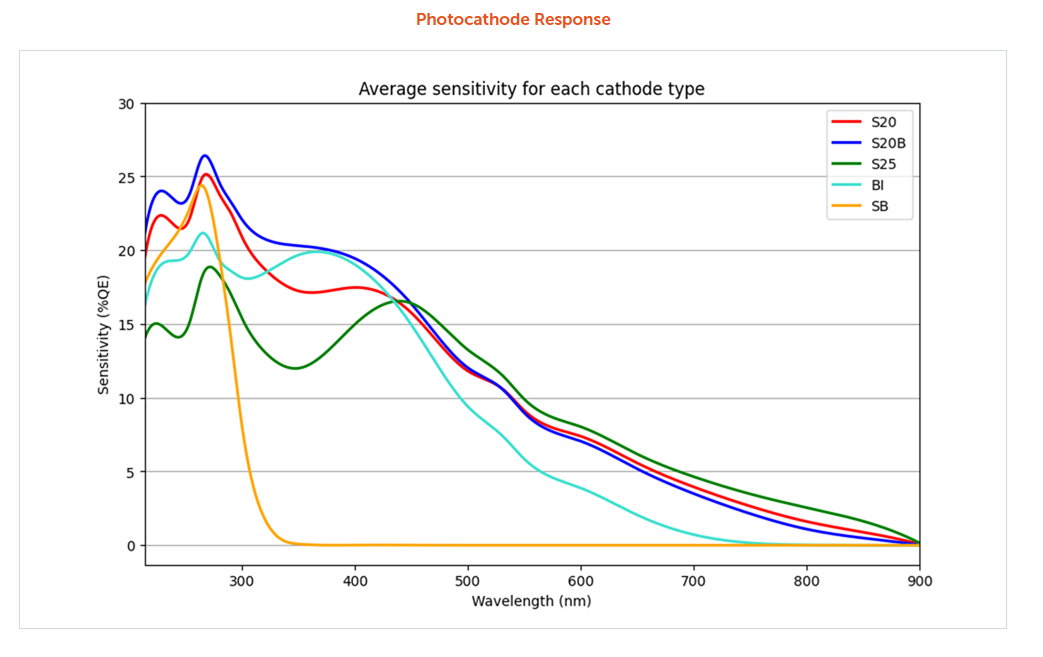
The photocathodes contribute significantly to noise, since thermal electrons in semiconductors are always generated in parallel with the desired signal (and even more so in materials with a smaller bandgap and emission in the red and infrared spectral regions). These cannot be distinguished from photoelectrons and contribute to the dark current of the image intensifier. Typical values for dark current/dark noise are given in the following table:
| Photokathode | Dunkelstrom (cps/cm2) |
|---|---|
| S20 | > 200 |
| Low Noise S20 | 30-50 |
| Bialkali (BI) | 5-20 |
| Solar Blind (SB) | < 5 |
Multi-Channel Plates (MCPs): In very low-light conditions or at very high frame rates, a single amplification stage may sometimes be insufficient to sufficiently distinguish the received signal from noise. In such cases, it may be advantageous to incorporate multiple MCPs – and thus multiple amplification stages—to increase the gain. In addition to the grain size of the phosphor layer, the structure of the individual capillaries (arrangement/diameter) contributes most significantly to the achievable spatial resolution:
| Größe des Bildverstärkers (mm) | MCP Porengröße | Typ. Limitierende Auflösung (P43) |
|---|---|---|
| 18, 25 | 6/8 | 40 lp/mm |
| 40 | 10/12 | 26-36 lp/mm |
| 75, 150 | 25/32 | 10-15 lp/mm |
Phosphors: The electrons accelerated and multiplied in the MCP strike the phosphors, causing them to emit luminescence and converting the electrons back into visible light. The luminescence processes of commercially available phosphors have different quantum yields (efficiencies) and different decay times, which is an important factor at high frame rates. If the phosphor in the image intensifier remains excited for too long (longer than the gating time window or the exposure time), so-called ghost images occur.
The following table shows the various options offered by the phosphors:
| Typ | Farbe | Chem. Zusammensetzung | Emissionsmaximum (nm) | Effizienz (Photonen/Elektronen bei 5 kV) | Abklingzeit (µs von 100% zu 10% zu 1 %) |
|---|---|---|---|---|---|
| P11 | Blau | ZnS:Ag, Cl, oder ZnS:Zn | 446 | 120 | 3000/50000 |
| P20 | Grün | (Zn, Cd)S:Ag+ | 540 | 320 | 250/1000 |
| P24 | Grün | ZnO:Zn | 500 | 120 | 22000/>100000 |
| P43 | Grün | Gd2O2S:Tb3+ | 548 | 240 | 1200/2400 |
| P46 | Gelb-Grün | Y3Al5O12:Ce3+ | 530 | 55 | 0,3/0,9 |
| P47 | Blau | Y3SiO5:Ce3+ | 410 | 64 | 0,1/0,4 |
Output: There are various ways to transmit the image from the phosphor screen to the detector or another device for further processing, whether using conical optics (fiber taper), fiber optics, or glass, depending on the application.
Control and Gating: For more information on the control electronics or gating options, see “Accessories.”
The following list shows typical application examples. This allows you to estimate the performance of the image intensifiers with different photocathodes for various applications:
| Photokathode | Spektral- bereich (nm) | Absorptions- maximum (nm) | QE (%) | Photonic Gain (ph/ph) | EBI (typ./max.) | |
|---|---|---|---|---|---|---|
| Ph/cm2s | lux | |||||
| S20 | 175-800 | 400 | 21 | 1 MCP: 1 x 10⁴ 2 MCP: 2 x 10⁶ | 2000 | 2 x 10⁻⁷ |
| S20B | 175-800 | 260 | 30 | 1 MCP: 2 x 10⁴ 2 MCP: 4 x 10⁶ | 5000 | 2 x 10⁻⁷ |
| BI (Bialkali) | 175-700 | 350 | 21 | 1 MCP: 1 x 10⁴ 2 MCP: 3 x 10⁶ | 50 | 2 x 10⁻⁷ |
| S25 | 175-900 | 450 | 16 | 1 MCP: 1 x 10⁴ 2 MCP: 2 x 10⁶ | 20000 | 2 x 10⁻⁶ |
| SB (Solar Blind) | 175-340 | 270 | 24 | 1 MCP: 2 x 10⁴ 2 MCP: 3 x 10⁶ | 5 | n. a. |